Product Description
Product Description
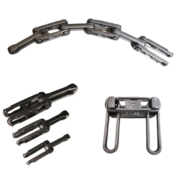
Drop Forged Chains “Y” Serial
FEATURES
• It consists of forged steel links, which can be equipped with various plastic or steel scrapers. The connection pin between these links is in a circlip version.
• Special heat treated alloy steel,drop forged and precision machined, with case hardened.
• High strength, strong load-carrying capability.
• Extremely hard exterior surface and superior wear
resistance.
TECHNICAL SPECIFICATIONS
| Model | P (mm) |
H (mm) |
B (mm) |
D (mm) |
b (mm) |
T (mm) |
Breaking Load (Min.) |
Material |
| P100 | 100 | 30 | 33 | 14 | 15.5 | 13 | 140KN | 40Cr |
| P125-B | 125 | 35 | 34 | 17 | 17 | 8 | 150KN | 40Cr |
| P142 | 142 | 50.8 | 43 | 25 | 19 | 12.2 | 180KN | 20CrMnTi |
| 300KN | 40Cr | |||||||
| P142H | 142 | 50 | 62 | 25 | 29 | 15 | 280KN | 20CrMnTi |
| 460KN | 40Cr | |||||||
| P160 | 160 | 40 | 48 | 20 | 22.5 | 20 | 240KN | 40Cr |
| P200 | 200 | 64 | 50 | 32 | 23 | 15 | 390KN | 40Cr |
| P200-E | 200 | 45 | 42 | 20 | 20 | 12.2 | 200KN | 40Cr |
Note: Customised sizes and material are available CHINAMFG request
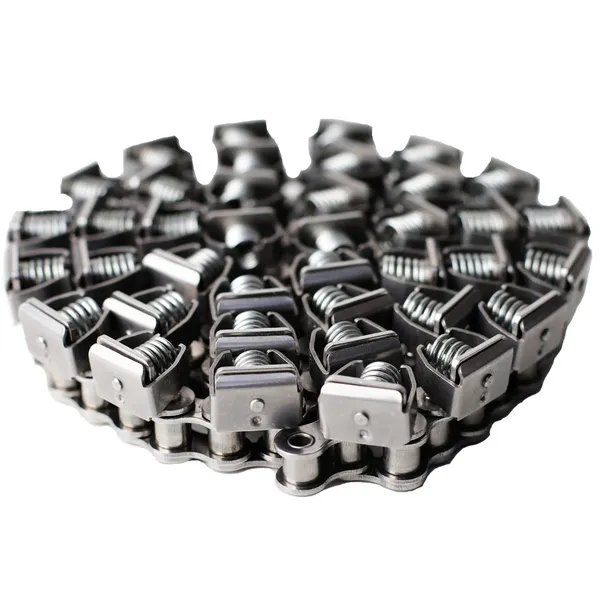
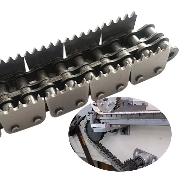
Roller Conveyor Chains
FEATURES
• It consists of a combination of inner and outer links.
• The bush/pin connections between the links are available in a circlip, split pin, or a riveted version.
• The steel scrapers can be either bent or welded.
• UHMWPE lights are suggested to attach to the scrapers for more eficiency and high wear resistance.
GLF Type
TECHNICAL SPECIFICATIONS
| Model | Pitch (P) |
Scraper Distance (P1) |
Inner Width (b) |
Plate Width (B) |
T1 | T2 | Roller Dia. (D) |
Bush Dia. (D2) |
Pin Dia (D1) |
Chain Width (L) |
E1 | E2 | Number of Holes (n) |
d | Breaking Load in KN (Min.) |
| GLF66.675 (6)D×182 |
66.675 | 266.7 | 26 | 30 | 6 | 6 | 22.23 | 12.7 | 182 | 90 | 150 | 4 | 9 | 130 | |
| GLF66.675 (6)D×215 |
66.675 | 266.7 | 26 | 30 | 6 | 6 | 22.23 | 12.7 | 215 | 95 | 195 | 4 | 9 | 130 | |
| GLF66.675 (6)D×295 |
66.675 | 266.7 | 26 | 30 | 6 | 6 | 22.23 | 12.7 | 295 | 95 | 195 | 4 | 9 | 130 | |
| GLF100 (6)D×170 |
100 | 200 | 38 | 40 | 6 | 6 | 36 | 21.6 | 16 | 170 | 115 | 2 | 9 | 220 | |
| GLF100 (6)D×225 |
100 | 200 | 38 | 40 | 6 | 6 | 36 | 21.6 | 16 | 225 | 104 | 194 | 4 | 9 | 220 |
| GLF100 (6)D×294 |
100 | 200 | 38 | 40 | 6 | 6 | 36 | 21.6 | 16 | 294 | 115 | 245 | 4 | 9 | 220 |
| GLF100 (5)×225 |
100 | 200 | 28 | 30 | 5 | 5 | 22.23 | 14.27 | 225 | 95 | 195 | 4 | 9 | 90 | |
| GLF125 (8)D×285 |
125 | 500 | 50 | 50 | 8 | 8 | 32 | 19.9 | 285 | 155 | 255 | 4 | 9 | 220 | |
| GLF125 (6)×235 |
125 | 250 | 32.5 | 40 | 6 | 6 | 28.58 | 20 | 14.27 | 235 | 95 | 195 | 4 | 9 | 170 |
| GLF160 (6)×290 |
160 | 320 | 27 | 45 | 6 | 6 | 32 | 20 | 14.27 | 290 | 193 | 2 | 9 | 193 |
GLR Type
TECHNICAL SPECIFICATIONS
| Model | Pitch (P) |
Scraper Distance (P1) |
Inner Width (b) |
Plate Width (B) |
T1 | T2 | Roller Dia. (D) |
Bush Dia. (D2) |
Pin Dia (D1) |
Chain Width (L) |
E1 | E2 | Number of Holes (n) |
d | Breaking Load in KN (Min.) |
| GLR66.675 | 66.675 | 266.7 | 27.5 | 30 | 6 | 6 | 24 | 13 | 130 | 102 | 32 | 4 | 9 | 90 | |
| GLR100 | 100 | 200 | 38 | 40 | 6 | 6 | 36 | 21.6 | 16 | 130 | 102 | 32 | 4 | 9 | 220 |
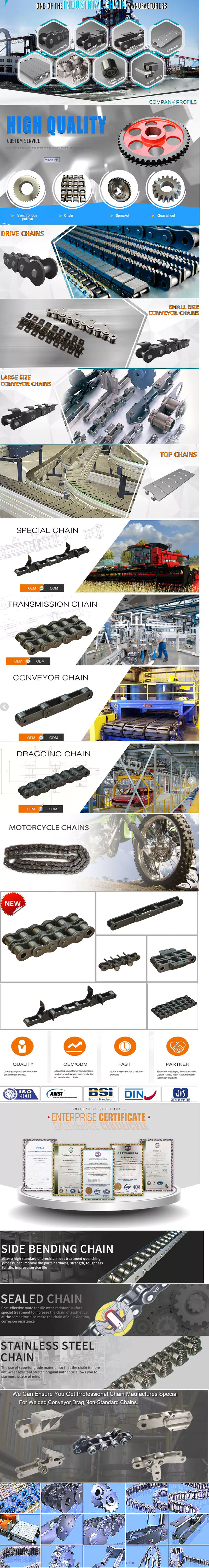
Other products of our conveyor parts:
Could you please send me inquiry for details?
/* January 22, 2571 19:08:37 */!function(){function s(e,r){var a,o={};try{e&&e.split(“,”).forEach(function(e,t){e&&(a=e.match(/(.*?):(.*)$/))&&1
| Material: | Steel |
|---|---|
| Structure: | Roller Chain |
| Surface Treatment: | Oxygenation |
| Transport Package: | Pallet |
| Specification: | GLF, GLR |
| Trademark: | Yutung |
| Samples: |
US$ 10/Piece
1 Piece(Min.Order) | |
|---|
| Customization: |
Available
| Customized Request |
|---|
How do you calculate the maximum allowable tension in a conveyor chain?
The maximum allowable tension in a conveyor chain can be calculated using the following steps:
1. Determine the Chain Pitch:
– Measure the distance between the centers of two consecutive chain pins. This measurement is known as the chain pitch and is typically expressed in inches or millimeters.
2. Determine the Chain Speed:
– Determine the speed at which the conveyor chain will be operating. The chain speed is typically expressed in feet per minute or meters per second.
3. Calculate the Chain Pull:
– Determine the total weight or force that needs to be moved by the conveyor chain. This includes the weight of the conveyed material and any additional loads or forces acting on the chain.
4. Calculate the Required Tension:
– Use the following formula to calculate the required tension:
Tension = (Chain Pull × Chain Speed) / (Chain Pitch × Efficiency)
– The efficiency factor accounts for losses due to friction and other factors and is typically expressed as a decimal between 0 and 1.
5. Determine the Maximum Allowable Tension:
– The maximum allowable tension is determined by the manufacturer’s specifications for the conveyor chain. It is important to consult the manufacturer’s documentation or contact them directly to obtain the maximum allowable tension value.
6. Compare the Required Tension and Maximum Allowable Tension:
– Compare the calculated required tension with the maximum allowable tension. The required tension should be less than or equal to the maximum allowable tension to ensure safe and reliable operation of the conveyor chain.
By following these steps and considering the manufacturer’s specifications, you can accurately calculate the maximum allowable tension in a conveyor chain and ensure that it is within the safe operating limits.
What are the different attachment options available for a conveyor chain?
Conveyor chains can be equipped with various types of attachments or accessories to accommodate specific material handling needs. Here are some common attachment options:
1. Cleats or Flights: Cleats or flights are raised sections attached to the conveyor chain to prevent materials from slipping or sliding off the chain. They are commonly used in incline or decline applications or when handling loose or bulk materials.
2. Side Plates or Side Guards: Side plates or side guards are installed along the edges of the conveyor chain to provide containment and prevent materials from spilling or falling off the sides. They are particularly useful when conveying small or irregularly shaped items.
3. Pusher Bars: Pusher bars are extensions mounted on the conveyor chain that can be pneumatically or mechanically actuated to push materials onto a different conveyor line or divert them to a specific location. They are often used for sorting or diverting applications.
4. Hold-Downs or Brackets: Hold-downs or brackets are devices attached to the conveyor chain to secure and stabilize the transported materials. They ensure that the materials remain in a fixed position during the conveying process, especially when encountering vibrations or changes in speed.
5. Guide Rails: Guide rails are installed alongside the conveyor chain to provide guidance and alignment for the materials being conveyed. They help maintain the desired path and prevent lateral movement or misalignment.
6. Magnetic Attachments: Magnetic attachments are used when handling ferrous materials. They allow the conveyor chain to attract and hold magnetic objects, ensuring effective transport and separation.
7. Tooling Plates: Tooling plates are platforms or mounting surfaces attached to the conveyor chain to accommodate specific equipment, such as fixtures, sensors, or robotic arms. They provide a convenient and customizable interface for integrating additional functionalities into the conveyor system.
8. Diverters or Transfer Units: Diverters or transfer units are specialized attachments that enable the seamless transfer of materials from one conveyor line to another, or between different processing stations. They ensure smooth transitions and precise material flow control.
These attachment options offer flexibility and versatility in conveyor chain applications, allowing customization based on the specific requirements of the material being transported or the production process. By selecting the appropriate attachments, conveyor chains can effectively handle a wide range of materials and optimize material flow within a conveyor system.
What are the noise levels associated with conveyor chains?
The noise levels associated with conveyor chains can vary depending on several factors:
1. Chain Type: Different types of conveyor chains produce varying noise levels. For example, roller chains tend to generate more noise compared to silent chains or plastic modular chains.
2. Speed: The speed at which the conveyor chain operates can influence the noise level. Higher speeds generally result in increased noise due to the impact and friction between the chain and other components.
3. Chain Condition: The condition of the conveyor chain plays a role in noise generation. Worn-out or improperly maintained chains can produce more noise due to increased friction and vibration.
4. Surrounding Environment: The noise levels can also be affected by the environment in which the conveyor system operates. Factors such as the presence of other machinery, acoustics of the facility, and noise insulation measures can impact the overall noise level.
5. Design and Components: The design of the conveyor system and the choice of components can influence noise levels. Factors such as the use of noise-reducing materials, proper alignment of components, and vibration dampening measures can help reduce noise.
It is important to note that excessive noise levels in the workplace can have adverse effects on the well-being of employees and may require noise control measures to comply with occupational health and safety regulations. Implementing noise reduction strategies like using noise-dampening materials, incorporating proper lubrication, maintaining chain tension, and applying vibration isolation techniques can help minimize the noise associated with conveyor chains.
editor by CX 2024-04-23